CMC has over 25 years of experience with using FEA software since 1996, specifically, FEMAP and NX NASTRAN. We have the capability to perform many types of analysis for multiple industries, not just the marine industry.
We are capable of performing these types of FEA tasks on a wide variety of structures and parts, including:
Static Analysis
Nonlinear Analysis
Buckling Analysis
Dynamic Analysis (Modal, Transient, and Random Response)
What sets us apart from many other FEA analysts is our 35 years of hands-on “deck plate” experience on many different types of vessels in operations, new construction, repair, and overhaul environments.
We can help your company leverage the benefits of using FEA to answer “what if” questions and simulate the behavior of a complex structure subjected to various loading conditions. Some benefits include:
Evaluate alternatives for a better end product.
Design optimization
Develop better manufacturing and construction methods.
Simulate heavy lifting and the affects on the distortion of the item being lifted or the foundation of the crane.
Dramatically reduce testing costs and shorten time to market.
Here are some examples of completed FEA projects:
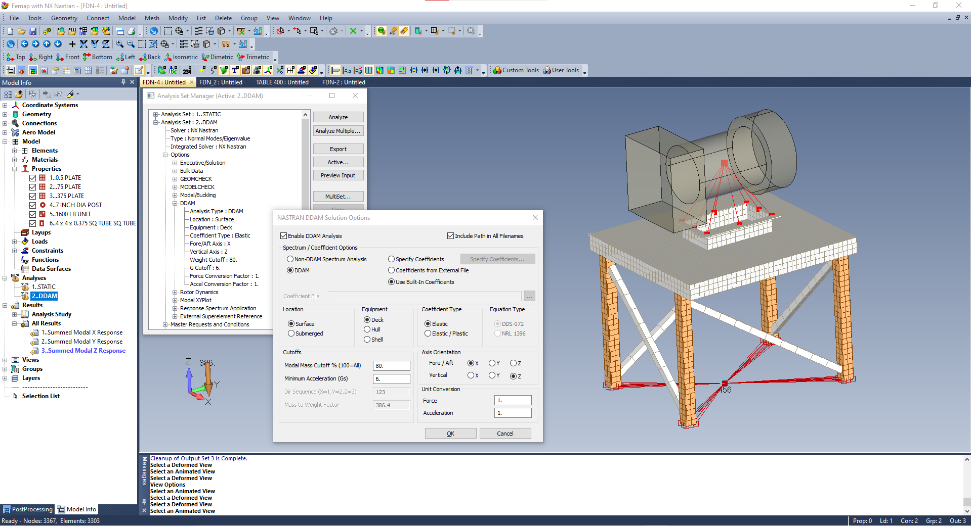
DDAM Shock Analysis
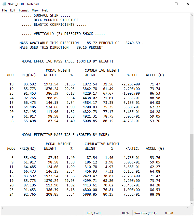
DDAM shock analysis simulates the interaction between the shock-loaded component and its fixed structure as the free motion of a naval vessel in water produces a higher shock spectrum than a heavy structure would when mounted to a terrestrial surface. It takes interaction into account in relation to the mass of the equipment, its mounting location, and the orientation of the equipment on the vessel.
Engineers use Finite Element Analysis (FEA) software including FEMAP and NX NASTRAN to verify designs using DDAM computer simulations that model the known characteristics of underwater explosion phenomena as well as the surface ship or submarine body responses to shock loading and application of a shock spectra order to apply the appropriate shock responses at the mountings of shipboard equipment (e.g., masts, propulsion shafts, rudders, rudderstocks, bearings, and other critical structures) due to underwater explosions. The analytical process is described in NAVSEA 0908-LP-000-3010, Shock Design Criteria for Surface Ships, which provides technical criteria for shock design calculations, and provides general background and educational material concerning application of the DDAM.
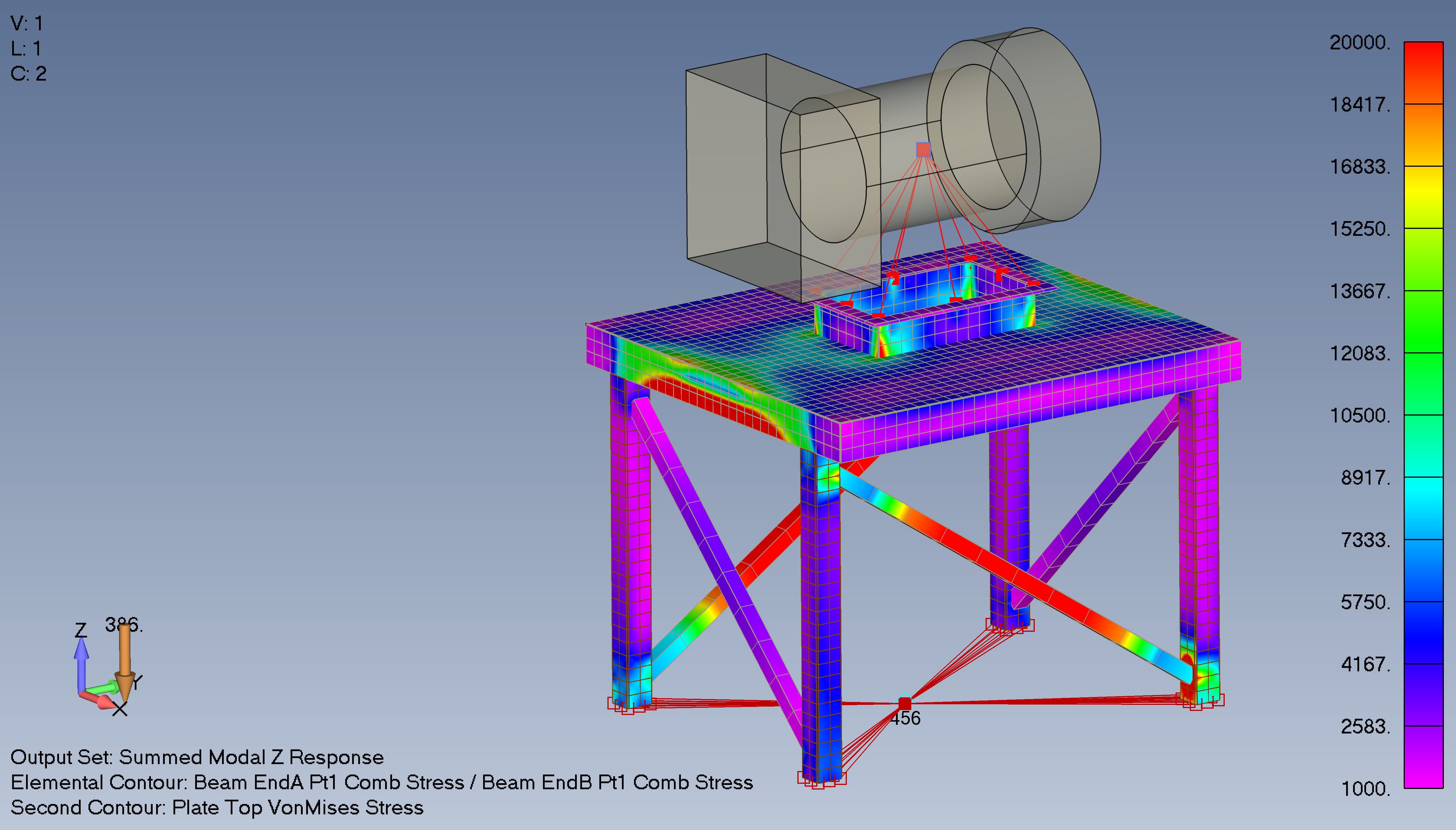
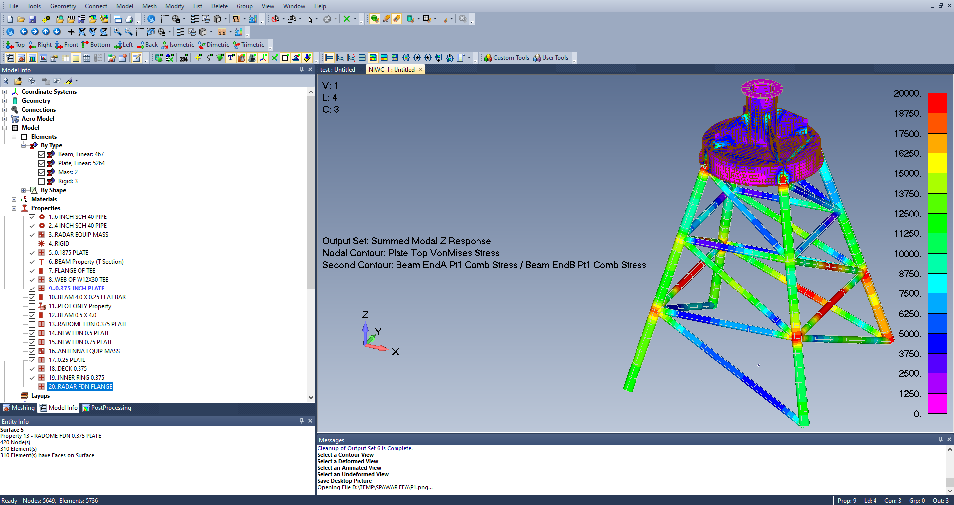
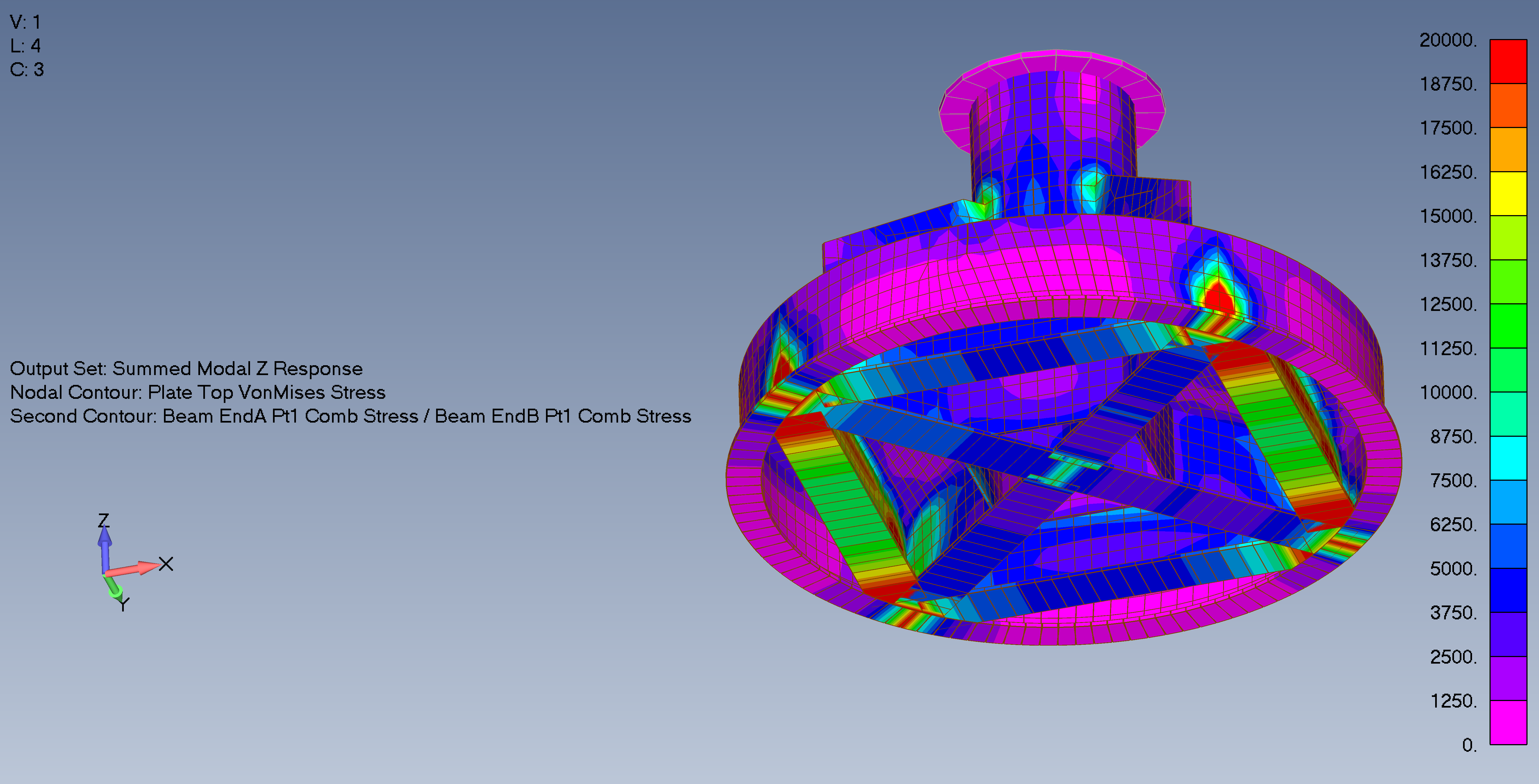
The models below are representations of typical shipboard foundations that would require a DDAM shock analysis.
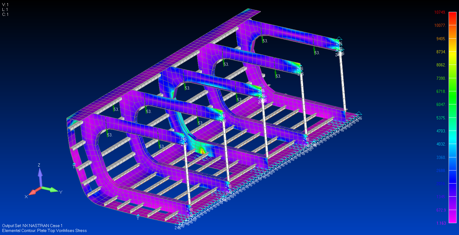
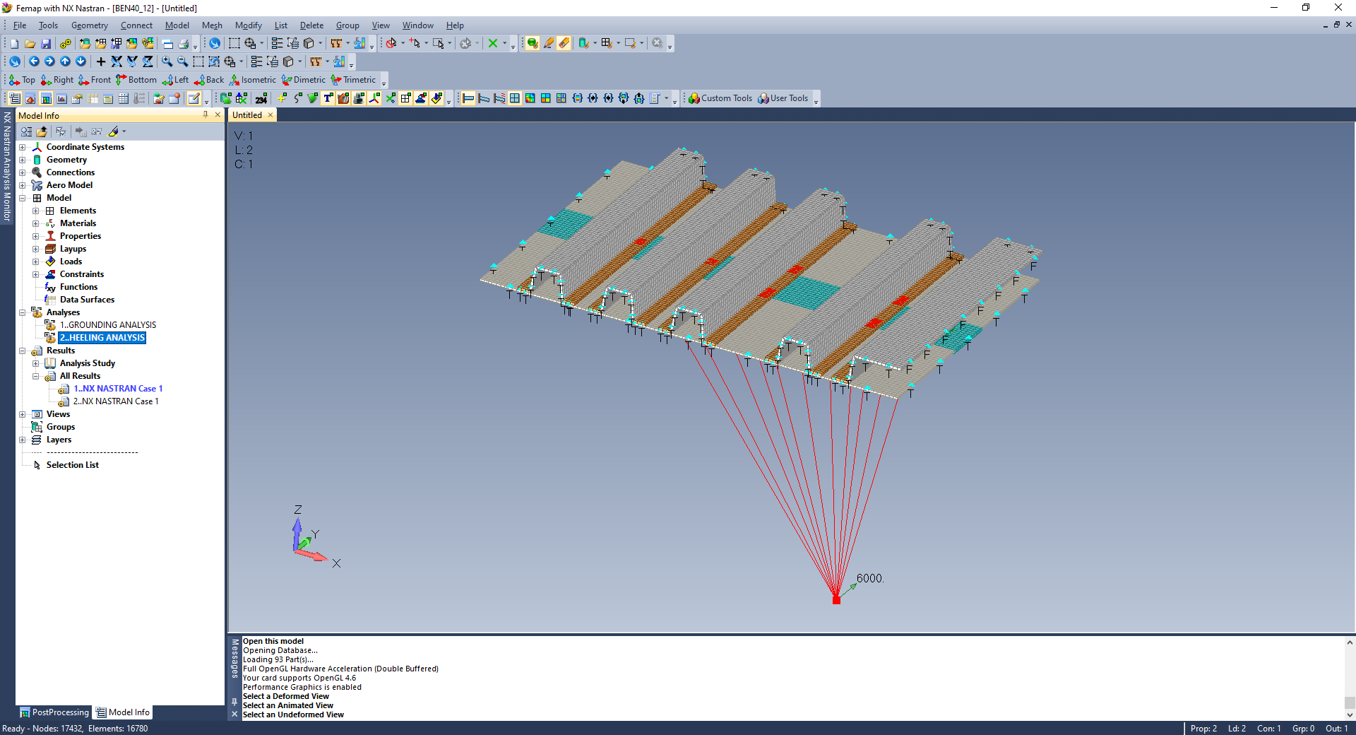
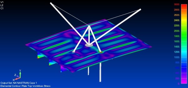
Beaneteau Oceanis 40 Simulation of Loading the Hull Grid Structure Due to Heeling and Hard Grounding