CMC was tasked by Seaward Services, Inc. to provide additional Naval Architecture and Drafting support for the USNS GUAM MEF Conversion at Detyens Shipyards, Inc. One of the tasks was to perform an informal Finite Element Analysis (FEA) study of a critical area of the modified stern deck area that supported a custom engineered aluminum column (post). The design was considered complete and approved already. In this case, program management wanted a higher level of confidence that there would not be any structural issues. What made this situation unique was that the cross section of the deck was not the typical plate with stiffeners, it was an engineered lightweight “plank” section, which is commonly used by Austal for these types of vessels.
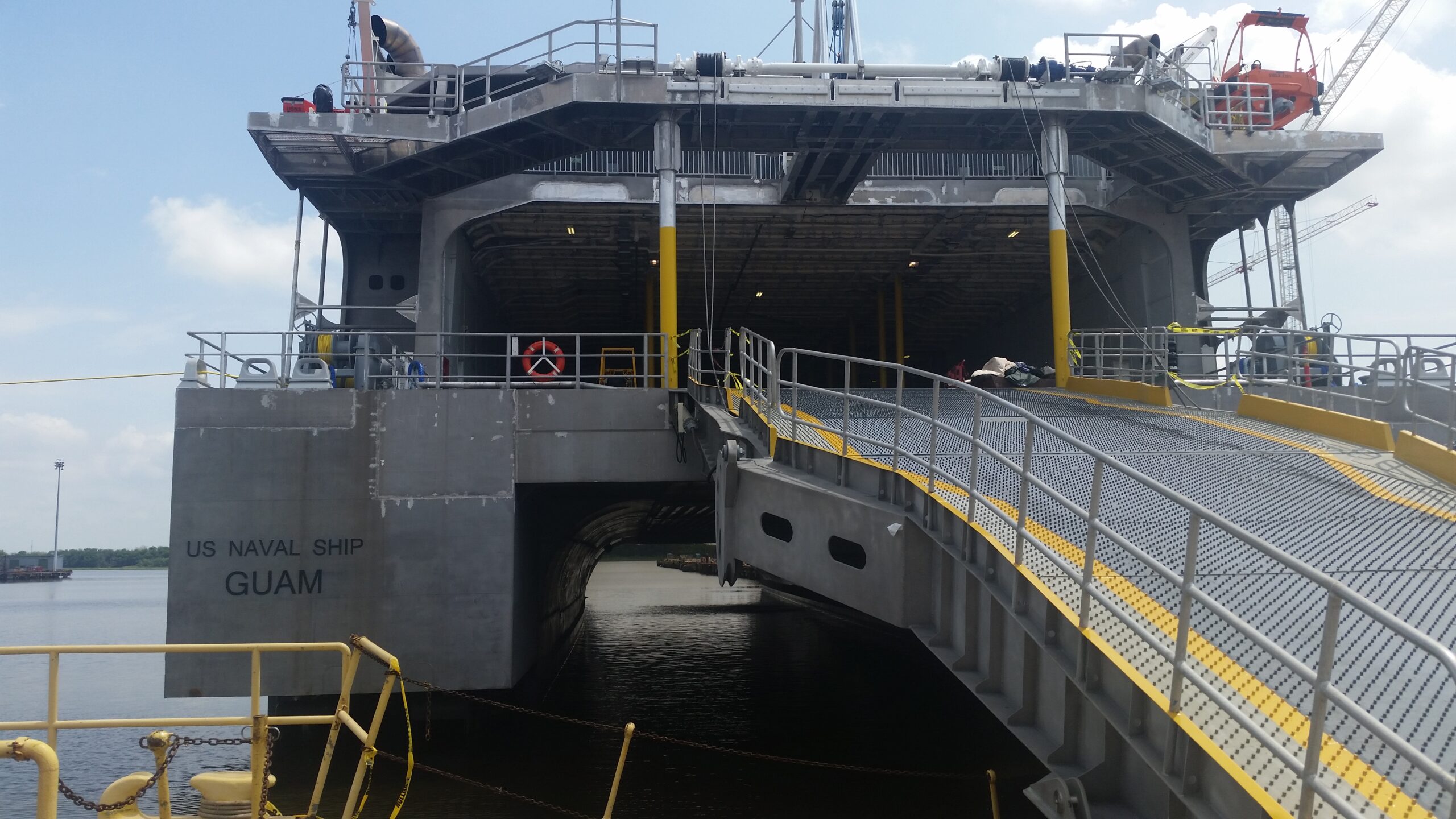
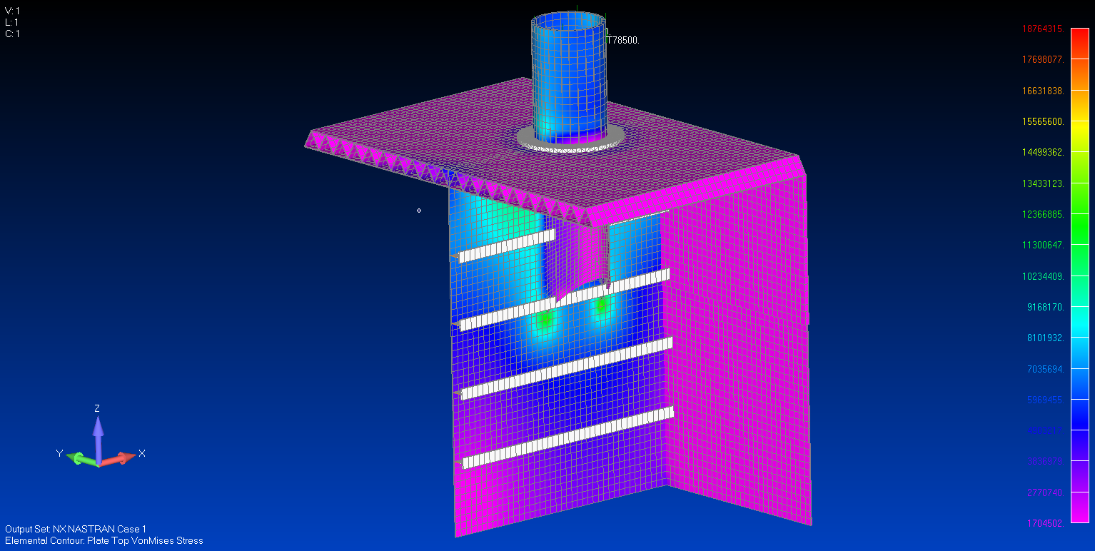
In the photo above, on the forward side of the stern ramp there are two posts between upper deck (ramp winch location) and the main deck. CMC performed an FEA of the local area at the base of the post on the main deck. FEMAP and NX NASTRAN was used for modeling the structure and performing the FEA.
With FEMAP, the next step in modeling is meshing all of the structure with the correct properties. For this model, we used plate elements for the deck (plank top, bottom, internals), bulkheads, and pipe (column). Solid elements were used for the doubler plate between the pipe and deck. Beam elements were used for the longitudinal bulkhead stiffeners. FEMAP and NX NASTRAN provided the capability to define “glued” contact , which we took full advantage of in this case in areas where it is very difficult to align the mesh nodes between different structural elements.
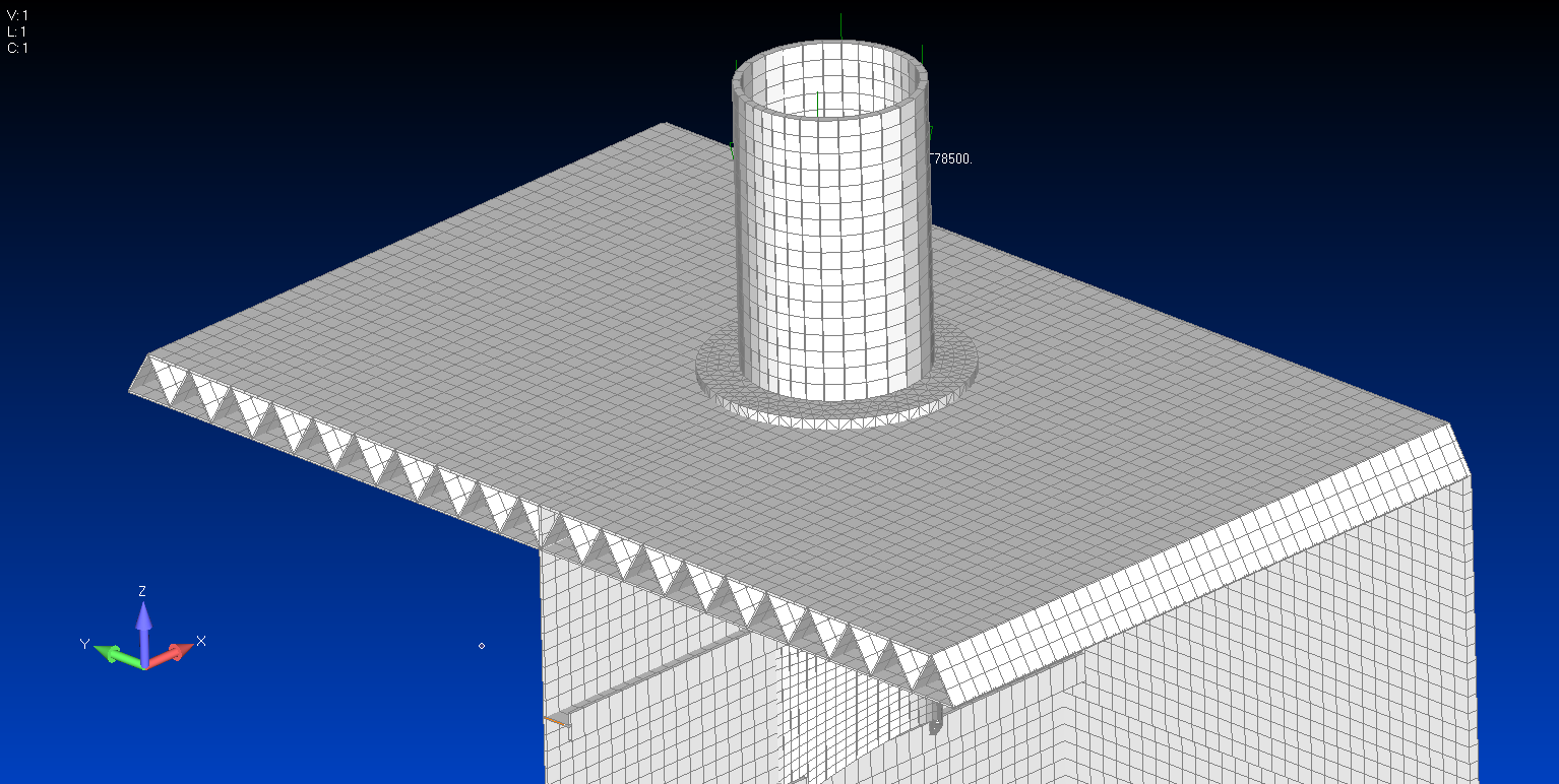
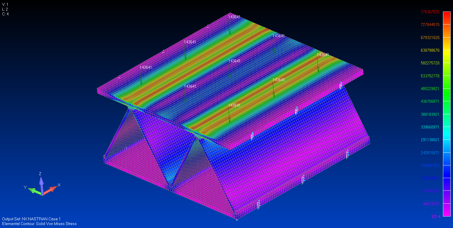
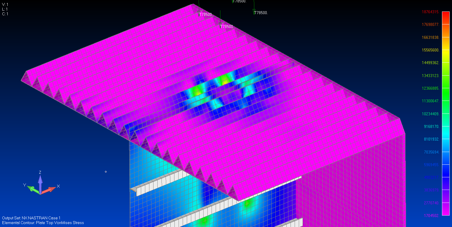
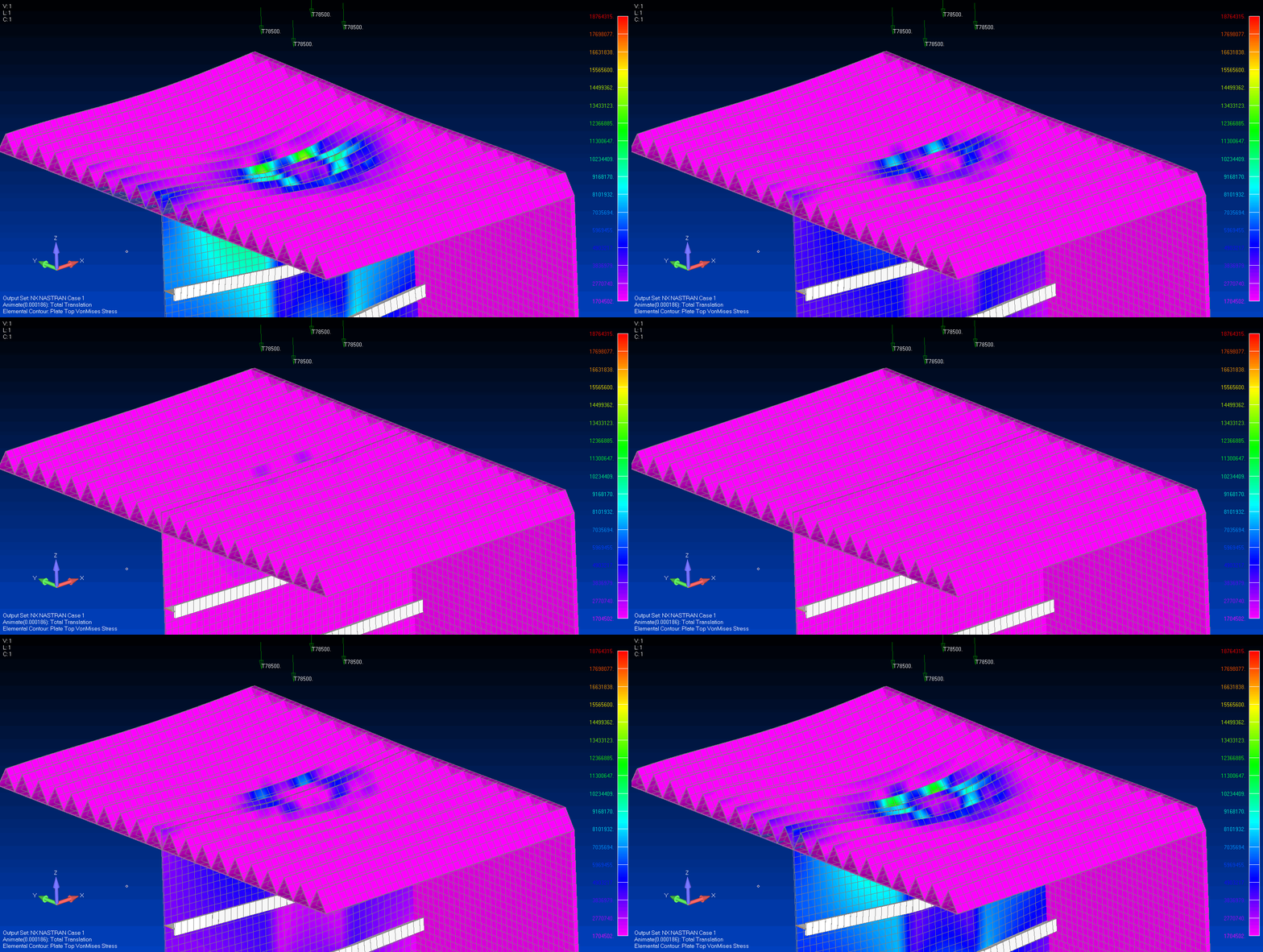
Boundary conditions, constraints, and loading was applied to the model in order to conservatively represent the worst case loading from raising the stern ramp. Before running the model, we wanted to have an understanding of how the “Plank” Deck section would behave from a stress point of view. The plank section model below shows the results of this study and it also validated our approach to modeling the plank deck:
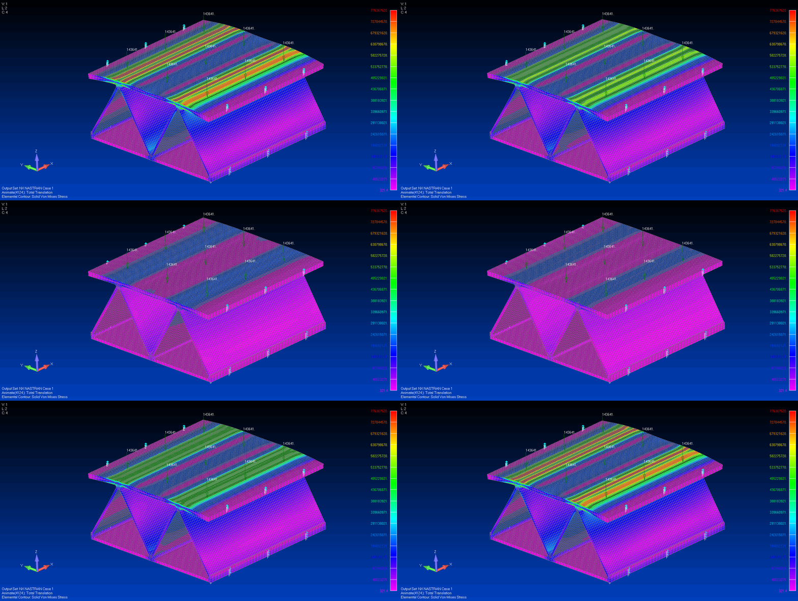
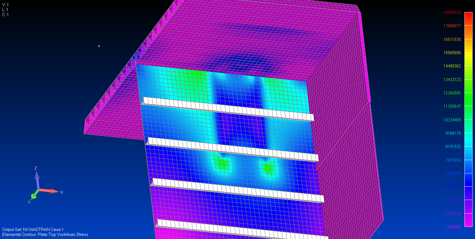
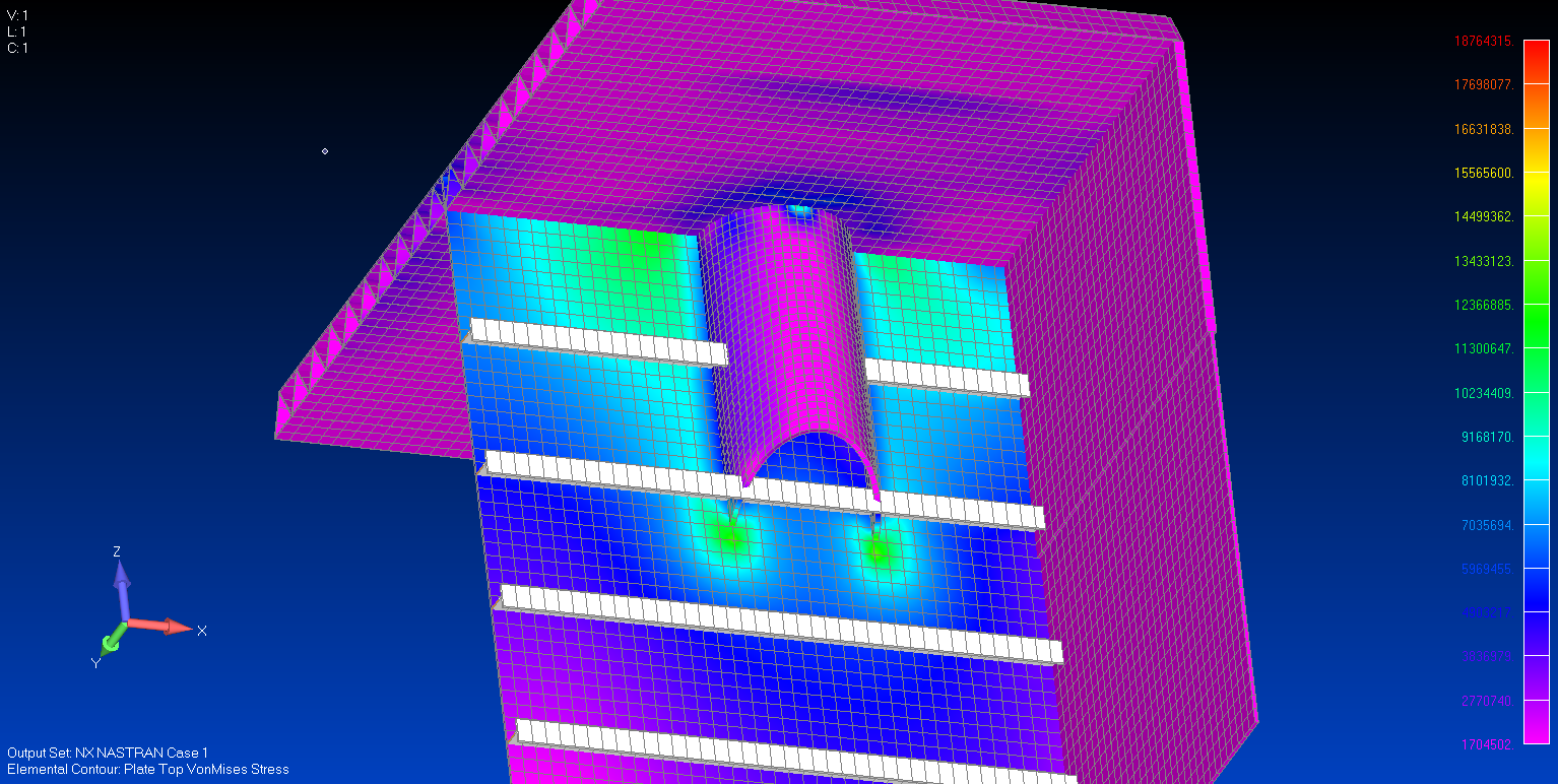
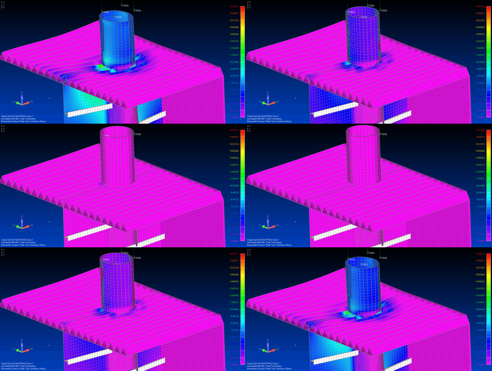
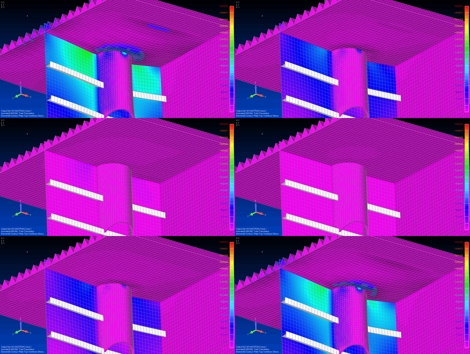
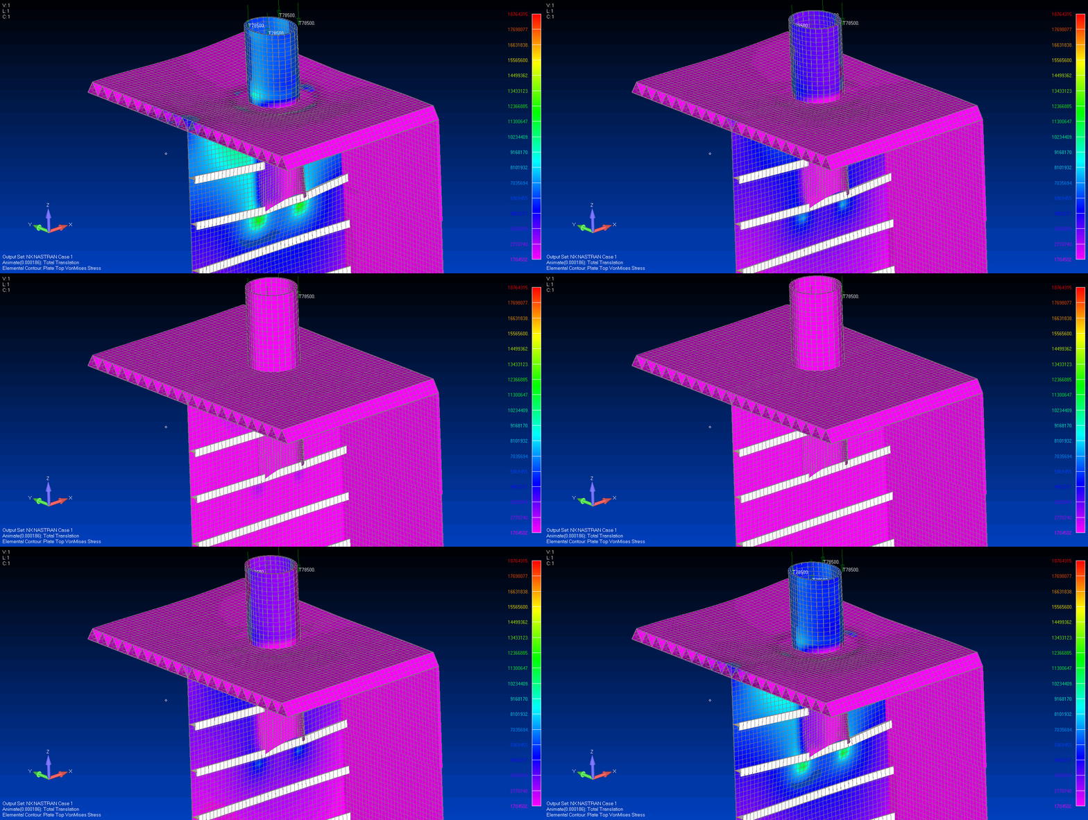
The screen shots to follow show results from the FEA, with various views shown with certain structural components turned off for post-processing. We concluded that for this study, the model was adequately built, and both the as-designed and as-built installation did not pose any problems in terms of excessive stress. Note: The stress value units in the plots are Pascals. The exaggerated scale animations aid in verifying that the structure is modeled, meshed, loaded, and constrained properly.
The results were shared with Seaward Services program management. They had one less thing to worry about.
This study for the USNS GUAM is a great example of how useful Finite Element Analysis (FEA) is when evaluating stress and deflections with ship structures. At Charleston Marine Consulting, we use Siemens FEMAP and NX NASTRAN FEA software , which is the industry standard.
