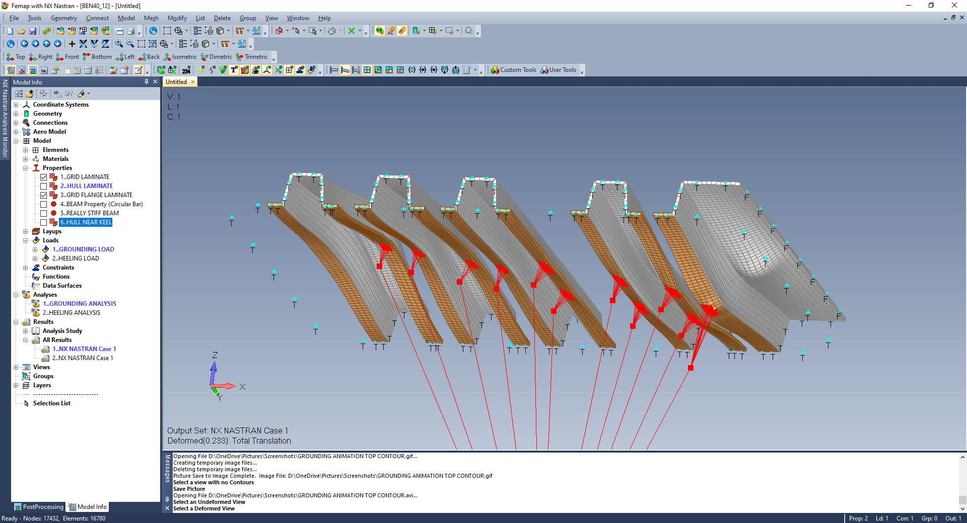
Description of FEA Modeling of Beneteau Oceanis 40 Sailing Yacht (Images above):
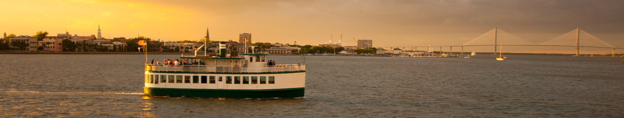
I own a 2009 Beneteau Oceanis 40 sailing yacht named “Karma” that I’ve spent the last several years outfitting for serious offshore cruising from the southern Caribbean Islands all the way up the East Coast to Nova Scotia. In mid-2020, I phased out of supporting Detyens Shipyard in Charleston in order to take some time off and do some cruising. So far, we have cruised the Bahamas and soon we will head down to the many islands of the Caribbean.
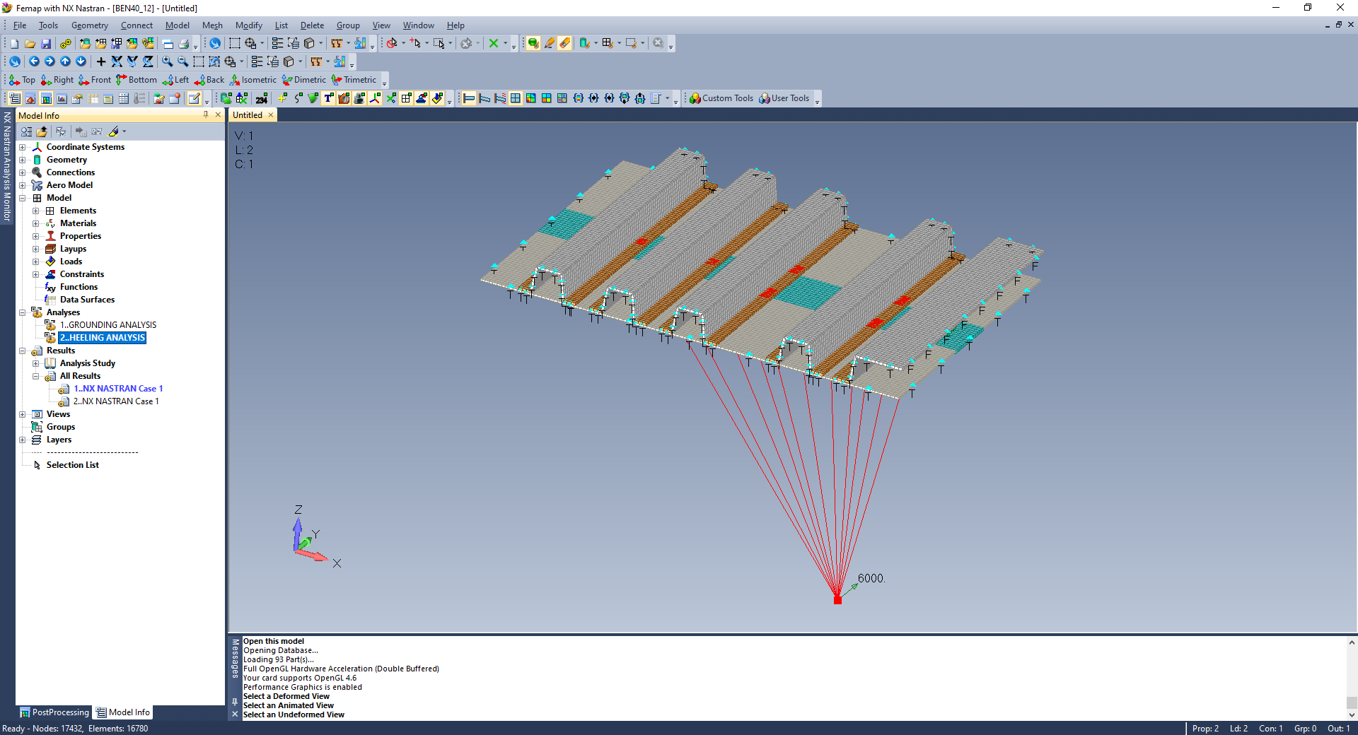
As a practicing Naval Architect with a toolbox that includes FEMAP and NX NASTRAN for serious Finite Element Analysis (FEA), just for kicks I decided to explore the simulation of what would be a horrible event for any sailboat owner – a hard grounding. The most difficult part of this is estimating what that force would be. There are so many variables that come into play such as the boat speed and what the object is hitting the keel. Of course, a large submerged rock that does not budge is the worst case scenario.
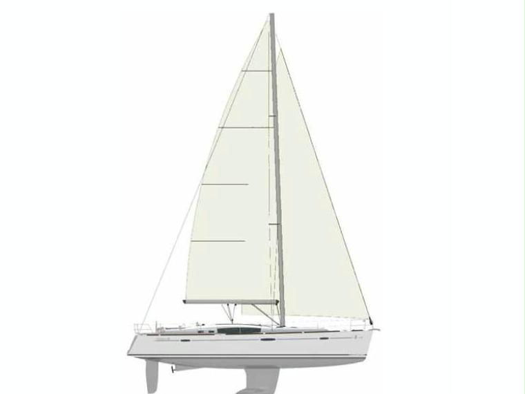
This type of event is particularly damaging for any yacht hull, particularly one built in a similar manner to Beneteau that utilizes a combination of a bolted-on keel and a composite structural grid that is molded separately from the hull and glued to the hull in one piece with a “chemical bond” while the hull is still in the mold. It is also tabbed in place in certain key high-stress areas. To my knowledge, these other manufacturers also build hulls in a similar fashion: Hanse, Jeanneau, and Dufour. It should be noted that many hundreds of these yachts have been built over a period of 30+ years with countless miles of serious ocean passage making across oceans and the North Sea.
In spite of the great track record for this type of construction, you are asking for trouble if you run your boat at any speed into a submerged rock, which is kind of like driving a Ferrari sports car over a one foot high curb at 15 mph. It won’t kill you, but the repair bill will put a serious dent in your wallet.
Running aground on a sandy or muddy bottom with a gradual slope at low speed is fairly common, and the structure should be able to handle this without a failure (I have first hand knowledge of this). I call this a “soft” grounding. After any hard grounding, you should always inspect the grid/hull interface and the area around the keel bolts in the bilge under the floor boards for any signs of separation or stress cracks.
A more extreme hard grounding event on a submerged rock at anything more than a very slow speed has a high probability of doing damage on this type of boat. What typically happens is separation of the grid from the hull in the affected areas near the keel boats which could extend outboard from what was modeled.
I did not spend any time trying to calculate a load to use for the hard grounding because I was more interested in validating the general behavior of the FEA model. For simplification, I used the displacement of the boat as the grounding load (18,000 lb). It is easy to just run the model again with whatever load you wish.


Beneteau Oceanis 40 FEA Final Notes:
This was a great opportunity for me to explore some great capabilities of FEMAP and NX NASTRAN (I’m running Version 12.0). I’ve been a huge fan of this FEA Package since 1996 when I worked as a Sales Engineer selling MSC NASTRAN for Windows (FEMAP bundled with NASTRAN). My territory was from the East Coast to Colorado (I travelled a lot). I admit that I am biased, but hands down, FEMAP bundled with NX NASTRAN is the best general purpose FEA software on the market and I’m glad I made the investment many years ago.
I spent an hour on my boat taking as-built measurements of the hull grid in the area of the bolted-on keel, then built the geometry model with surfaces in FEMAP. In particular, I took advantage of these particular capabilities of FEMAP throughout the FEA process:
- Geometry modeling from scratch all within FEMAP
- Modeling laminate structure with the ability to get as detailed as you want with the number and direction of ply’s and material properties.
- Glued contact between composite transverse frame flanges of the grid and the hull.
- Deformed plots to verify proper model behavior.
- Animated plots to verify proper model behavior.
- Detailed contour plots of stresses, displacements, and failure indices of every ply of the composite laminates.
- Contour plots of the forces and traction specifically within the “glued” contact areas.
Disclaimer: The FEA model of my Beneteau 40 Hull Grid is an approximation of the structure and simulated response when subjected to various loading conditions such as a hard grounding or heeling. The loads are transmitted into the hull and grid locally via the keel and keel boat attachments. I don’t know the precise thickness of the hull, frames, flanges, etc, nor do I know the exact GRP layup schedule, so I made an educated guess. I did take measurements of spacing and depth of the transverse frames. The hull bottom in the keel attachment area was modelled to be flat for simplification.
The Results and Conclusion: The FEA model showed realistic behavior simulating a hard grounding event along with a typical loading due to heeling loads from the 6,000 lb keel. Stresses and displacements seemed to be realistic based on the assumptions made. Of course, the loading due to any hard grounding is subjective and very difficult to determine, which is why I always go very slow when the water is shallow!
The golden rule of FEA still applies: Garbage In = Garbage Out.
In general, I have a better understanding of the structural integrity and limits of the hull structure grid design on my Beneteau Oceanis 40, so it will not stop me from sailing offshore to Bermuda or St. Barts!
Thanks for reading!